A Message Mover via Means of Electrical Egress, or We've Lost Our Marbles Ch. 2
Shocking dispatches
Plastic tubing and marbles aren’t very practical over long distances, but we can take the same principle and apply it to a better method of transmission. Electrical signals propagating over lengths of copper wire are much less cumbersome to deal with. Let’s take a look at how that would work.
Using electrical signals to send information has several advantages. An electrical signal propagates through a wire at close to the speed of light. In addition, copper wire is strong and fairly flexible. If we apply a voltage to the end of a copper wire, we can measure the change in voltage at the other end of that wire almost instantaneously. However, voltage is a relative measurement. If you hook up a voltmeter to 2 wires and it displays 5v (5 volts), that means that the second wire is 5v higher than the first. Since voltage is the the relative difference between 2 points, we need at least 2 points to measure. Therefore we need a second copper wire to serve as that reference. We will call that reference wire the ground wire, and we’ll call the other one the signal wire.
Let’s set up a battery on one side and a voltmeter on the other side.

Our voltmeter is measuring the difference between one point, the positive side of the battery, and another point, the negative side of the battery. In this case, the negative side is the reference point. Since the positive side is 5 volts higher than the negative side, the display reads 5v. If we instead use the positive side as the reference point (by reversing the connections), the display would read -5v because the negative side is 5 volts below the reference.
Can you see how we can use this system to replace our marble tube? We put Alice in a room with a 12v battery and 2 wires. The wires run all the way to Bob’s room where they are connected to a voltmeter with a display. When Alice connects one wire to the positive side and one wire to the negative side of the battery, 12v is shown on Bob’s display. When Alice disconnects one or both wires, the display shows 0v.

If we say that 12 V is Yes or 1, and 0v is No or 0, then we can replace the marbles with this system and every other layer keeps working exactly the same. Just like we did with the carrier pigeons.
The longest marble
There’s one minor problem. With marbles, adding space between digits is automatically handled for you. There’s no way to send a “long” marble that contains more than one bit. With a continuous electrical signal, we need to decide beforehand how to break up a long signal into individual bits.
With marbles there were 3 possible states: no marble, a green marble, and a red marble. In the new electrical system, there are only 2 states: 0v and 12v. Without an equivalent “no marble” default state, there is no easy way to represent spaces between bits. If Alice did nothing at all, the system was in the “no marble” state. We need to pick a default value for our new system. It’s either going to be 0v or 12v.
Let’s pick 0v just to make it easy. We call this default state the idle state. But 0v also represents a 0 bit in addition to being the idle state–how does Bob know whether Alice is sending nothing or a 0? How does he know whether 1 1 1 1 1 is five 1s or just a single 1 and that Alice left it connected for too long?
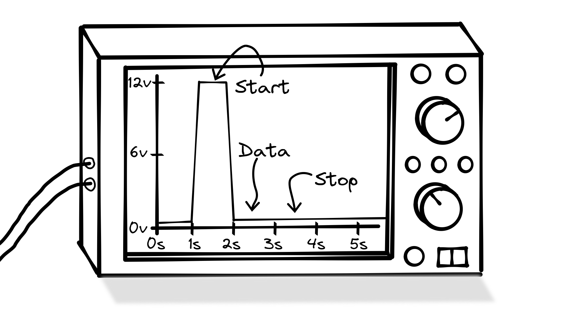
Here’s what we can do. If Alice isn’t sending a message, she leaves one of the wires disconnected and Bob sees a 0v on his voltmeter display. This is the idle state. When Alice wants to send either a 0 or a 1, she needs a way to tell Bob that the signal is no longer idle. To do this she connects the wire to the battery for 1 second. This changes signal to 12v, and this is called the start bit. After the start bit, she sends a data bit. If she wants to send a 1, she leaves it connected for 1 second. If she wants to send a 0, she disconnects the battery for 1 second. After that she disconnects the wire and leaves it that way for at least one second–this is called the stop bit.
With this system, anytime Bob sees a jump from 0v to 12v he knows that a data bit is on the way. Then if he waits for 1 second, he’ll see the value of the data bit. Therefore every message consists of 3 parts. The start bit, which is 1 second of 12v; the data bit, which is 1 second of either 0v or 12v depending on whether it’s a 0 or a 1; and the stop bit, which is 1 second of 0v.
To demonstrate what this looks like, let’s hook up an oscilloscope to our machine. An oscilloscope is similar to a voltmeter except that instead of showing the voltage at only the current moment, an oscilloscope plots the voltage over time. Here’s an oscilloscope showing what happens when Alice sends a 1 bit. Notice that the y axis is the measured voltage between the signal and ground wires, and the x axis is time.

And here’s what it looks like when Alice sends a 0 bit.
Labor contracting contrivances
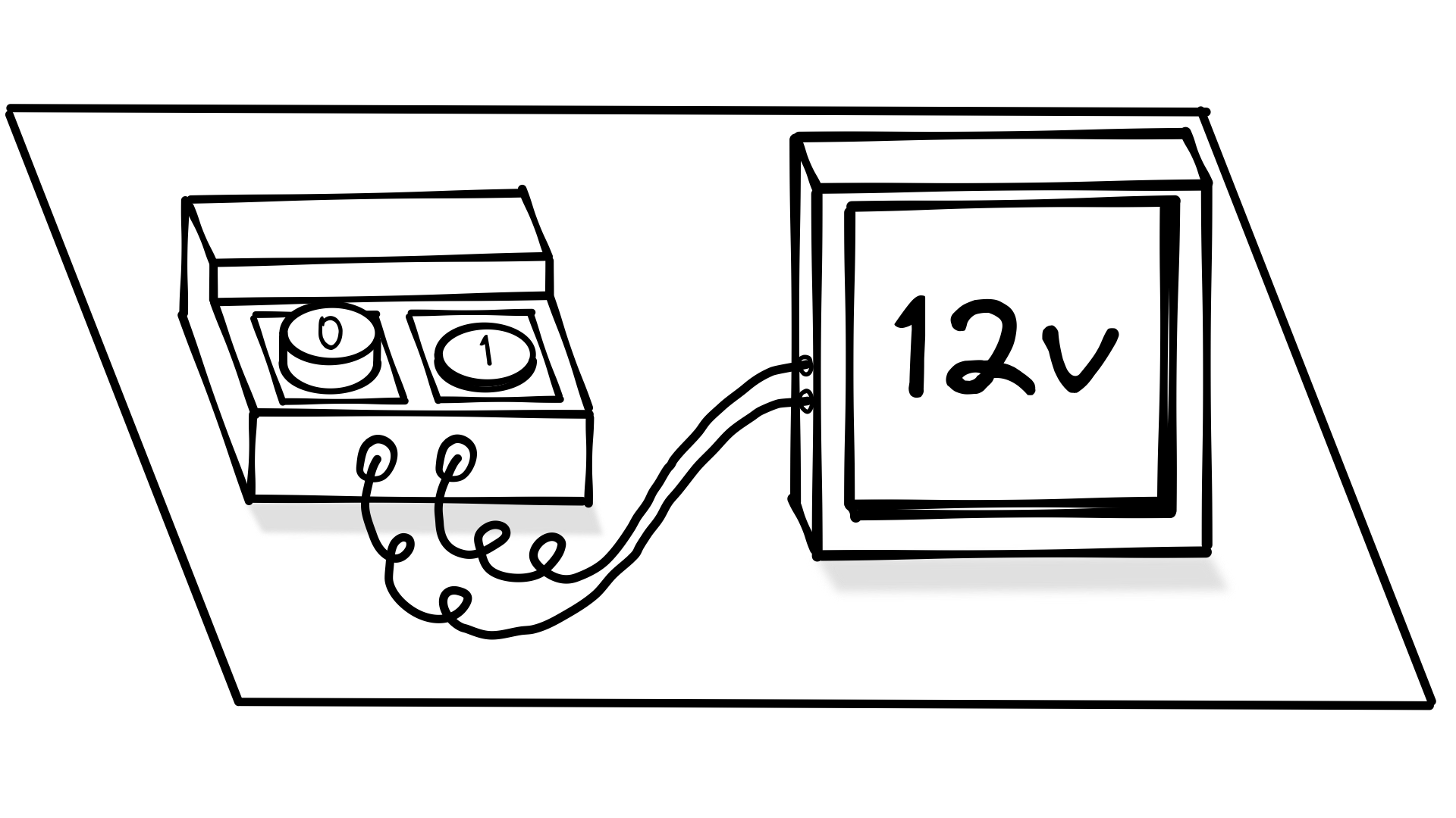
This all seems like a lot for Alice to manage. Is there anything we can do to make her job easier? What if we built a machine that has connections for 2 wires and a button pad with 2 buttons. The first button is labeled 1, and second button is labeled 0. By default the machine sets the value of the signal wire to 0v. This is the idle state. No bits are being sent.
When someone presses the 1, the machine replicates what Alice would have done manually. It sets the signal wire to 12v above the ground wire for a second to let Bob know that a data bit is about to be on the way. After that, it keeps the signal wire at 12v for one second to send the data bit. Finally it sends the stop bit by setting the signal wire to ground for at least another second. This exactly replicates the signal we observed on the oscilloscope when Alice sent a 1 bit manually.
When someone presses the 0, the machine replicates what Alice does when she sends a 0 bit manually. This exactly replicates the 2nd signal we saw on the oscilloscope above.
Now that we’ve made Alice’s job easier, what about Bob’s? Instead of a voltmeter, we can install a machine with an internal oscilloscope that can automatically detect when Alice sends a 1 or a 0 and show 1 or 0 on its display. Here’s how it works.
When the signal is idle, the machine waits for a rising edge to detect the start bit. A rising edge is when the value of the signal changes from 0v to 12v. It’s called a rising edge because that’s what it looks like on an oscilloscope.
After it sees the rising edge, it stops for 1 second to wait for the data bit. If the value of the data bit is 12v it records a 1, but if the value is 0v it records a 0. Then it waits another second for the stop bit. Assuming the value of the stop bit is 0v (if it’s not then something bad has happened and the machine will display an error), the machine records that the signal is back in the idle state and it shows the value of the data bit on the display. Finally, it begins waiting for the rising edge of another start bit.
A discrete continuum
If you’ve noticed, the value on the oscilloscope jumps from 0v to 12v very quickly. However, very quickly isn’t instantaneously. Let’s zoom in on the x axis to 10 milliseconds so we can see that a bit better.
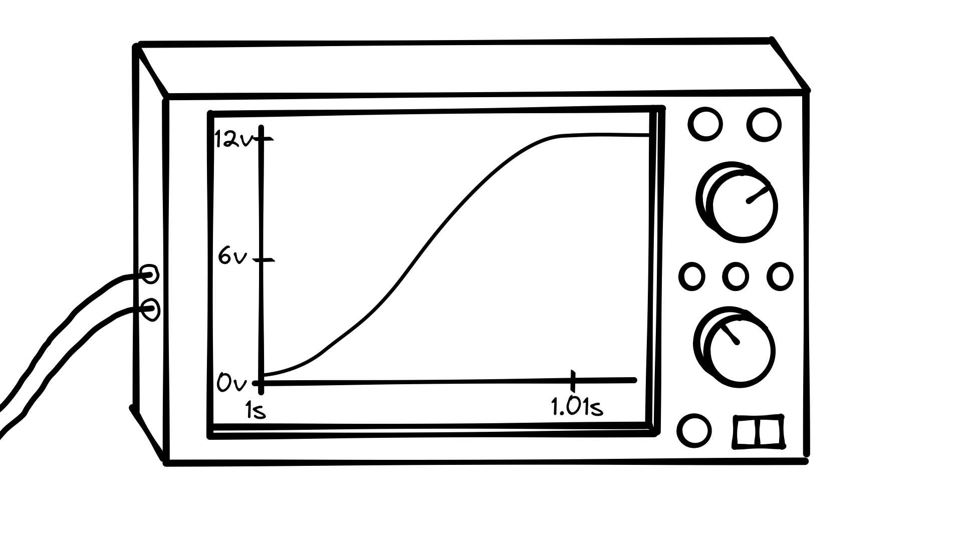
For some small amount of time, the signal takes on many different values as it climbs towards 12 V.
This is another difference between our new system and the tube of marbles. A marble is either there or it’s not; you can’t roll fractions of a marble down a tube. Marbles are countable with whole numbers. We call this property discrete. Voltage can take on any number from negative infinity all the way up to infinity. The difference in voltage between the signal and ground wires could be 0.1v, 3.5v, 11.9v, 11.99v, 11.999999v, etc…
In fact, it’s almost impossible to put exactly 12v on the signal wire because it is susceptible to noise and interference from the environment, and the voltage drops over the length of the wire. The longer the signal wire, the more susceptible it is to these issues. This places practical limits on the length of a signal wire.
We can zoom in on our oscilloscope’s y-axis to see that what looks like a straight line actually has many small fluctuations.

To account for all these issues, we need to accept a range of values. Let’s say that anything between 0 and 3 volts is a 0, and anything between 9 and 12 volts is a 1. Those values are somewhat arbitrary, but they give us some wiggle room to handle longer and shorter wires and the other fluctuations that can happen in an electrical circuit, as we discussed. Any values between 3 and 9 volts are considered to be in an undetermined state, and reading those values will cause an error. Having a large buffer value between the 0 and 1 state is important because we’d rather a voltage fluctuation cause an error than cause a 0 to turn to a 1 or a 1 to turn to a 0.
To make sure we don’t read undetermined values, after detecting the rising edge, our machine will need to wait slightly longer than the duration of the start bit before reading the value of the data bit. That way if the data bit is a 0, we don’t accidentally read a value below between 3 and 9 volts, during the falling edge (while the signal is dropping from the 12v start bit to the 0v data bit).
One more thing. Now that a machine is reading the values instead of a person, we can make the bit durations much shorter. Instead of 1 second for the starting bit, 1 second for the data bit, and 1 second for the stop bit, we can shorten this to 1 millisecond each. This allows us to send data at a faster rate.
At the end of the day, what we’ve done here is to build 2 devices. The first device is the bit transmitter that takes a discrete binary value–a 0 or 1–and converts it into a continuous analog value–an electrical signal between 0 and 3 volts or 9 and 12 volts.
The second device is the bit receiver that takes the continuous analog electrical signal and converts it back into a discrete binary value.

Fire the first floor
Now that we have our bit sending machine working, have you noticed anything about the new setup? We don’t really need the first floor anymore. We can give the bit transmitter keypad to 2nd floor Alice. Instead of sending down bits to the first floor, she can just press the buttons herself. And in Bob’s building, we can give 2nd floor Bob the display that shows a 1 or a 0. Now the first floor Alice and Bob are gone, but the second floor Bob and Alice don’t have to do any additional work.
Can we keep going with this to replace even more Alices and Bobs? You guessed it. Of course we can! 2nd floor Alice needs to take a letter, lookup the binary code in her table, and then press that sequence of buttons on the bit transmitter keypad. We can make a machine that does that for us.
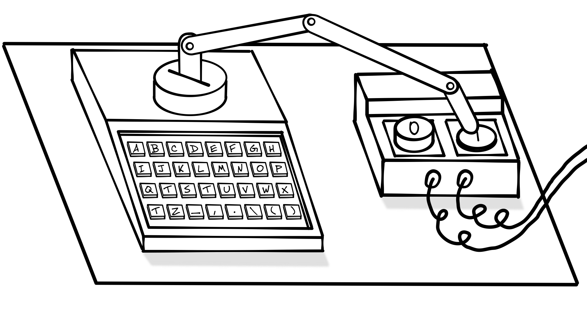
Imagine a machine that has a keyboard on it. One key for each letter we can send. When you press a key, the machine looks up the binary code for you in its internal copy of the letter to binary table. The machine then sends the correct sequence to the bit transmitter. We could build this machine so that it has a mechanical finger that physically presses the correct buttons on the bit transmitter, one button after the other, until it has entered the entire sequence. For example, you’d press J on the keyboard, the machine would look up the sequence and the machine would enter 0 1 0 0 1 into the bit transmitter.
Microcontroller mania
However, physically pressing the buttons is cumbersome and error-prone. If we take a moment to examine how buttons on electronic devices actually work, we can see that there is a much easier way to directly connect our letter writer to our bit transmitter.
Many small electronic devices are built using something called a microcontroller. A microcontroller is essentially a very small computer built as a single small package called an integrated circuit or microchip.

The microcontroller looks a bit like a small insect. The body houses the computer, which runs programs that can be loaded onto the microcontroller. The legs are called pins. Some of the pins can only do one thing. For instance the ground and power pins are hooked up to a power supply or battery to provide power to run the microcontroller. Other pins are called GPIO (General Purpose Input/Output) pins. GPIO pins can be programmed to function as either an input or an output.
Output
If we set a GPIO pin to act as an output, we can write code to change the voltage of that pin (the voltage of a pin is always measured in reference to the ground pin).
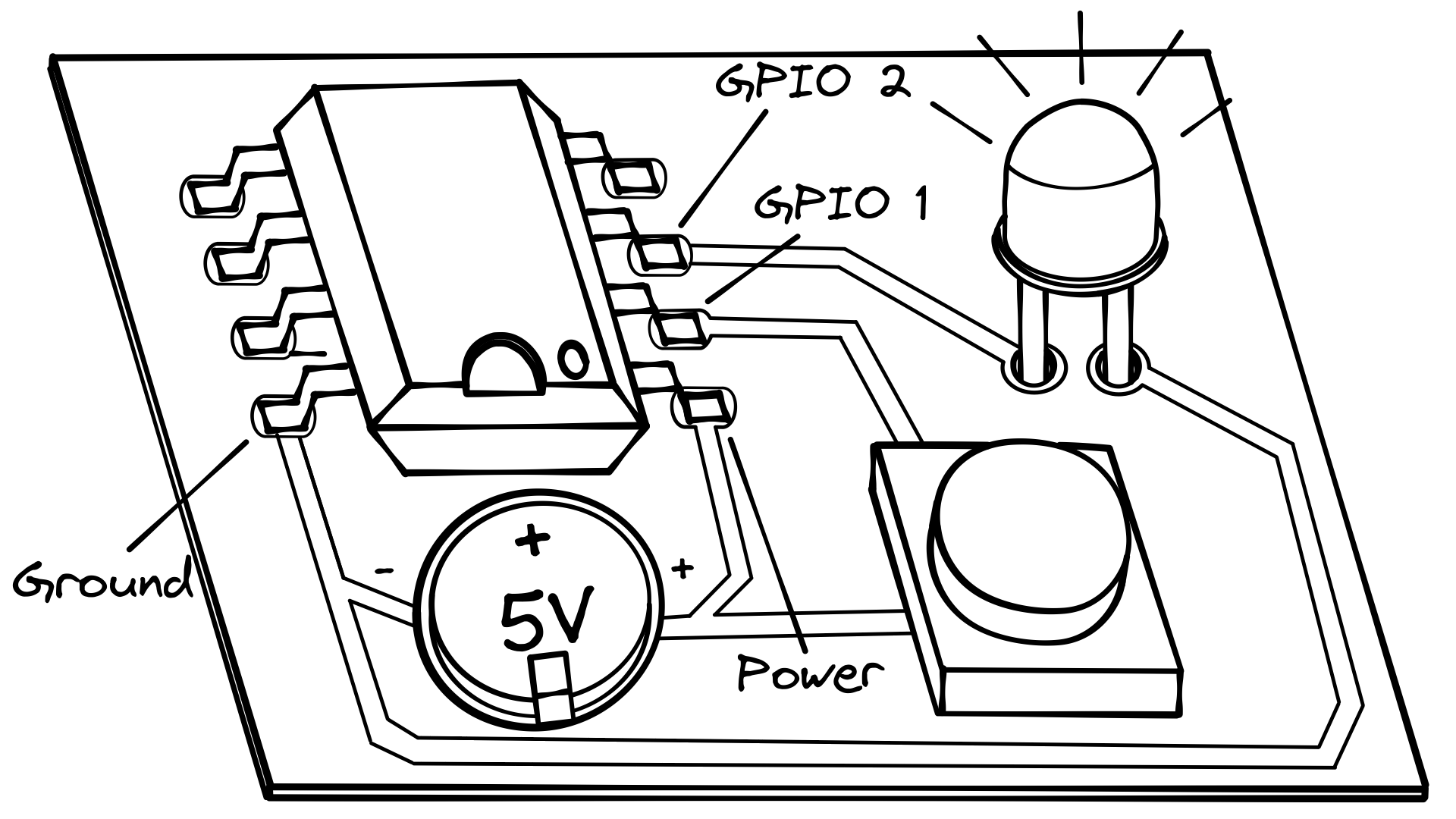
Imagine that we want to blink a small LED light 10 times. Here’s how we could wire up a hypothetical microcontroller to do that. The microcontroller, the coin cell battery, and the LED are all attached to a surface called a printed circuit board (PCB). Each component is soldered to the PCB, and the components are connected to each other by connections called traces. You can think of a trace as a flat copper wire. The coin cell battery has a positive and negative side just like any other battery. In this case, the top of the battery is positive and the bottom is negative. The negative side of the battery will act as ground in our circuit.

One side of the LED is connected to GPIO 1, while the other side of the LED, the negative side of the battery, and the ground pin of the microcontroller are all connected together. Finally, the positive side of the battery is connected to the microcontroller’s power pin.
Here is the example code that we could run on our microcontroller to blink the LED:
Set GPIO 1 to output mode
Repeat 10 times
  Set GPIO 1 high
  Wait 1 second
  Set GPIO 1 low
  Wait 1 second
Set GPIO high means to set the pin to the same voltage as the positive side of the battery. In this case that’s 5v above ground. Remember that voltage is a range rather than an exact number, so 5v will be something like 4.7v to 5.3v. Set GPIO to low means to set the pin to ground (0v).
As long as GPIO 1 is set to high, there is a difference of 5v between GPIO 1 and ground. This will cause current to flow between GPIO 1 and ground passing through the LED, and the LED will light up. If GPIO 1 is set to low, there is no voltage difference between GPIO 1 and ground (0v), so no current will flow through the LED, and it won’t light up.
Essentially our code sets GPIO 1 to output mode, turns on the LED for 1 second, turns it off for 1 second, and repeats until it has done this a total of 10 times.
Input
If you set a GPIO pin to act as an input, that means you can essentially use it like the voltmeter/oscilloscope on the receiving end of our bit transmitter. An input pin will let you detect whether a wire is high or low.
Imagine that we instead of blinking a light, we want it to stay lit while a button is pressed.
We take our previous circuit and add a button to it. A button is really just a small switch that works like a light switch. When the button is pressed, it completes a circuit and when it’s released it breaks a circuit. When the circuit is complete, current flows, and when the circuit is broken, no current flows.

If we connect one side of the button to our input pin (GPIO 1 in this case), and one side of the button to our 3v power, as long as the button is released, our input pin will read low. While the button is pressed, the input pin will read high.
We can write some code that will only light up if the button is pressed (and therefore the input pin is high).
Here’s the example code:
Set GPIO 1 to input mode
Set GPIO 2 to output mode
Repeat forever
  If GPIO 1 is high then
    Set GPIO 2 high
  Else if GPIO 1 is low then
    Set GPIO 2 low
Look ma no fingers
How can we use what we just learned to hook up the letter writer output to the bit transmitter input? The bit transmitter input is just 2 buttons. Internally these buttons are wired up to input pins on a microcontroller.
Let’s take a look at what this circuit would look like. But first this circuit is starting to get a bit complicated. To make it easier to cram everything into one drawing, we’ll use a schematic instead of a more realistic drawing of the physical circuit board.
Schematics are like maps of a circuit. They use symbols to represent each component instead of realistic images. Here’s an example of the LED button pressing circuit we looked at above, so you can learn how to read a schematic.

The schematic is exactly equivalent to the drawing above, but with the appropriate symbols instead of images. Notice the symbols for the microcontroller, the LED, and the button. The traces are replaced with lines connecting the components. When drawing a schematic, we can take a few shortcuts. We don’t have to draw the battery; we can just draw the ground symbol and the voltage the battery provides (5v in this case). It’s also easier to draw the ground symbol and 5v multiple times instead of trying to draw multiple connections to one symbol. Look back and forth between the drawing and the schematic and make sure you understand how they are the same.
Now that you know how to read a schematic, here’s a schematic of our original bit transmitter.

Notice the new component–the transmitter. The transmitter is responsible for outputting 0v or 12v. The transmitter looks a lot like the microcontroller. Unlike the microcontroller, the transmitter isn’t programmable. It can’t run user uploaded code, and so we can’t use code to change the behavior of any of its pins.
On the left side of the transmitter, we have 1 input pin, High/Low. On the right side we have 2 output pins, Signal and Reference. Reference is always set to the same voltage as ground, but Signal changes depending on the input from High/Low. When High/Low is set low (0v), Signal is set low (0v). When High/Low is set high (5v), Signal is set high (12v).
It’s also important to remember that our microcontroller high vs low voltages are 5v and 0v respectively, but our bit transmitter output voltages are 12v and 0v. This difference in voltage is the entire reason we need the transmitter in the first place. The greater voltage range allows us to send signals over longer wires because larger voltages are less susceptible to noise, interference, and degradation. The microcontroller operates at 5v because it’s more efficient to operate at lower voltages when you can get away with it.
There are also 2 buttons, button 0 and button 1. Take a look at the bit transmitter drawing from before to remind yourself how the bit transmitter works. Remember that when someone presses button 0 the output is set to -5v and when someone presses button 1, the output is set to +5v. Let’s take a look at some code that shows exactly how that happens.
Set GPIO 1 to output mode
Set GPIO 4 to input mode
Set GPIO 5 to input mode

Repeat forever
  If GPIO 4 is high then
    Set GPIO 1 high
    Wait 1ms
    Set GPIO 1 high
    Wait 1ms
    Set GPIO 1 low
    Wait 1ms
  Else if GPIO 5 is high then
    Set GPIO 1 high
    Wait 1ms
    Set GPIO 1 low
    Wait 1ms
    Set GPIO 1 low
    Wait 1ms
  Else if neither is high then
    Set GPIO 1 low
If Alice presses button 1, we set GPIO 1 high (5v) for 1 ms (millisecond) to send the start bit, Then we keep GPIO 1 high for 1 ms to send the data bit. Finally, we set GPIO 1 low for 1 ms to send the stop bit.
If Alice presses button 0, we set GPIO 1 high (5v) for 1 ms (millisecond) to send the start bit, Then we set GPIO 1 low for 1 ms to send the data bit. Finally, we set GPIO 1 low for 1 ms to send the stop bit.
If no buttons are pressed, we set GPIO 1 low to signal the idle state.
Now that you know how the bit transmitter works, can you see how we can connect the letter writer directly to it?

We can ignore most of the internal workings of the letter writer, so we won’t draw those (we also won’t draw the keyboard). We’ll just draw it as a black box. It’s enough to know that the box has its own internal microcontroller. When a key is pressed on the keyboard, the microcontroller looks up the binary representation of the letter and then sets the appropriate output pins low or high.
Ground on the letter writer connects to ground on the bit transmitter so they share a reference voltage. We connect two output pins on the letter writer to two input pins to the input pins that were previously connected to the buttons. Now when we want to send a 0 from the letter writer to the bit transmitter we just need to set GPIO 1 on the letter writer high. And when we want to send a 1, we set GPIO 2 on the letter writer high. Both of these are the equivalent of manually pushing the 0 and 1 button.
For every letter pressed, the letter writer will send five bits. It will electronically “press the buttons” on the bit transmitter five times, once for each bit.
You may be wondering why we need the bit transmitter. Why can’t we just hook up the letter writer to the bit receiver directly? The connection between the letter writer and the bit transmitter is designed to be short range. To build a longer range transmission device, you need the additional hardware that the bit transmitter has. You could just build that hardware directly into the letter writer, but keeping them separate allows you to swap out the long range transmission layer like we swapped out the marbles for birds earlier. For example, we could swamp out the bit transmitter for one that uses fiber optics or even radio waves.
2nd floor Bob you’re out of a job
2nd floor Bob writes down the bits coming in from the bit receiver, waits until he has five, looks them up in his table, and sends them up.
Let’s build a machine similar to the letter writer, called the letter displayer.

The letter displayer will be hooked up to the bit receiver the same way we hooked up the letter writer and bit transmitter. The difference is the direction the data is flowing. The bit receiver will send the bits it gets from Alice’s bit transmitter to the letter displayer.
Reference and Signal are inputs not outputs, and High/Low is an output not an input. The High/Low pin will output the value coming from the Alice’s bit transmitter to the GPIO 4 pin on the microcontroller. GPIO 4 is acting as an input pin in this case. GPIO 1 and GPIO 2 are acting as outputs to send the bits along to the letter displayer’s 0 Input and 1 Input pins.
The letter displayer stores the bits until it has 5, then it looks up the corresponding letter in its lookup table and displays them on a display (because the letter displayer has a display, we can get rid of the display on the bit receiver). If we put the letter displayer on the 3rd floor, we will have completely gotten rid of the 2nd floor.

We’re back down to 2 rooms, but Alice and Bob now have much easier jobs. They don’t need to fiddle around with looking up binary encodings in a table. They don’t even need to know what the binary number system is.
There’s one tiny final improvement we can make. Bob’s screen only shows one letter at a time, so he still needs to write down the letters somewhere to read the entire message. We can fix this by swapping out the display for a printer that prints a tape of each letter as they come in. When the message is done, Bob can tear off the tape and he now has a copy of the entire message.
Alice also needs to send her message slowly–one letter at a time because Bob’s new printer is fairly slow, and if she sends letters faster than it can print them, they will be lost. To fix this we can add memory to Bob’s letter displayer (we could also add the memory to Alice’s letter writer if we wanted). If we do this, when she enters a message, she can type as fast as she likes and Bob’s letter displayer will store each letter. Then it will start printing them as fast as it can, and delete each letter as it prints it. This is called a buffer, and it’s a very important concept that we’ll discuss more later.
Back (and forth) to the future
It looks like we now have a full message passing system. A message mover via means of electrical egress if you will. Alice can send any message she wants to Bob. But what happens if Bob wants to respond? Or what if Bob wants to send the first message to Alice? Stay tuned for the next chapter to find out how we can add two-way message passing to our system!